| Author |
Topic |
|
|
twhite
133 Posts |
 Posted - 06 Nov 2009 : 11:01:17 Posted - 06 Nov 2009 : 11:01:17


|
Helios Platform Hardware Reference Manual (rev A  PDF 1.2 MB) PDF 1.2 MB)
Helios� is a programmable edge controller that provides a flexible application-ready hardware platform with enhanced wireless capabilities. It is based on the Catalyst Module which integrates with a base board and supporting peripheral devices. All electronics are housed in an enclosure. Three USB host ports for wireless devices and additional storage are accessible in the USB Bay located under the removable cover.
With the Helios platform, you can quickly and easily create an edge controller device, loaded with your application software that precisely meets your requirements. Several options are available allowing you to choose the hardware based on your specifications.
Using pre-certified wireless modules in the USB Bay, the Helios platform can be easily customized for any network. Software support includes Eurotech�s Everyware� Software Framework (ESF) offering simple to use APIs.
The Helios platform is available with the following operating systems: - Wind River Linux 3.0
- Windows� Embedded Standard
- Windows CE 6.0 (coming soon)
Features
* Processor
- Intel� Atom� processor at 1.1 GHz (up to 1.6 GHz options)
- Intel� System Controller Hub US15W
* Memory
- 512 MB DDR-2 DRAM (up to 2 GB options)
- Battery-backed real-time clock
- On-board PATA flash (option)
- External memory support
- -- USB disk drive
- -- CF card or SD card (option)
- -- 2.5-inch SATA drive (option)
* Communications
- Five USB 2.0 host ports operating at low, full, and high speeds
- -- Two general-purpose ports
- -- Three ports for plug-in USB modules and additional storage
- EIA-232 serial port or EIA-485 serial port (option)
- Gigabit Ethernet port
- GPS receiver with external antenna connection (option)
* User Interface, Display, and I/O
- Expansion connector supporting display, audio, and I/O options
- Nine LED indicators
- -- Power indicator
- -- SATA drive indicator
- -- Seven software-controllable indicators
- Software-readable push-button
* Power Supply
- 12 V DC power input (up to 36 V vehicle power input option)
- Software-switchable power output
Related Topics:
Helios LiveUSB Dev Kit Quick Start
Helios Platform Dev Kit w/ VGA Option Quick Start
Helios Platform WES Dev Kit CPDK7510 Quick Start
Updated 18 Nov 2009 by twhite
Updated 13 Oct 2010 by twhite
Updated 20 Oct 2010 by twhite
Did You Know?
We post changes, updates and errata to this topic as they become available. Subscribe to this topic or the forums to receive email notifications (see below).
You can get automatic email notifications when this or any topic is changed or replied to. Simply click the "Subscribe" icon ( ) on the Topic, Forum, or Category list to subscribe. You can unsubscribe ( ) on the Topic, Forum, or Category list to subscribe. You can unsubscribe ( ) just as quickly. ) just as quickly.
To cancel or manage subscriptions, click the "My Subscriptions" menu item at the upper right of any Forum page.
|
|
|
akidder
1519 Posts |
Posted - 05 Aug 2011 : 19:11:27
|
Resistance of Enclosure to Flame
The Helios enclosure is made with Cycoloy C2950HF, which is UL94 V-0 flame rated. |
 |
|
|
akidder
1519 Posts |
Posted - 15 Mar 2012 : 18:11:01
|
Caution: Vibration and Strain Relief for SMA Sockets
In your Helios installation, pay attention to the forces applied to the SMA connectors on the enclosure. Shear and pull forces, especially under long-term vibration, can damage or break the connector housings.
E.g. One installation that connected heavy, right-angle SMA-to-TNC adapters directly to the Helios SMA GPS connector caused the barrel of the connector to separate from its base.
We recommend that only cables be attached to the SMA sockets, and that the cables be strain-relieved in such a way that they will not put mechanical stress on the sockets.
|
|
|
|
twhite
133 Posts |
Posted - 19 Sep 2012 : 14:50:49
|
Erratum: Helios Platform Hardware Reference Manual, Rev A
On the PDF's page 19, in the table for section "Power Consumption":
- Line 2 should include a reference to Note 6 (not Note 7).
- Line 4, Inrush Current, should read 1.7 in the Max column.
- Line 5, should include a reference to Note 7 (not Note 8).
- Line 7, Inrush Current, should read 1.8 in the Max column.
|
|
|
|
akidder
1519 Posts |
Posted - 23 May 2013 : 17:50:06
|
EOL of Helios with WiFi (Feb-2013)
Helios products with WiFi are end of life. The Ubiquiti Ministation WIFI module is no longer in production. See PCN 13002 for details.
|
|
|
|
akidder
1519 Posts |
Posted - 11 Jun 2015 : 13:30:41
|
Creating a Helios Power Cable
Pin 1 of the Helios power connector is to the right, when looking at the rear panel of the Helios with "12VDC 2A" lettering below the connector.
Create a power cable as shown in the following image:
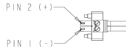
Excerpt from document 400124-30103E
The connector plugs into the Helios with the wire clamp screws down, and the positive(+) lead of the power supply wire to the left.
|
|
|
| |
Topic |
|
|
|