| Author |
Topic |
|
|
KnowledgeBase
296 Posts |
 Posted - 05 Nov 2002 : 17:11:23 Posted - 05 Nov 2002 : 17:11:23


|
Bitsy Plus User's Manual (PDF 731kB)
The Bitsy Plus is a full-featured single board computer using the SA-1110 StrongARM RISC microprocessor and SA-1111 Companion Chip. It has the same form factor as the Bitsy with a significant number of changes and enhancements. See the final chapter of the manual for a list of differences between the Bitsy and the Bitsy Plus.
Changes, updates and errata for this document will appear as replies to this topic as they become available.
modified May 5, 03 (ctacke) Link to rev A manual
Did you know?
You can get automatic email notifications when this, or any Topic is changed or replied to. Simply click the "Subscribe" icon ( ) on the Topic, Forum, or Category list to subscribe. You can unsubscribe ( ) on the Topic, Forum, or Category list to subscribe. You can unsubscribe ( ) just as quickly. ) just as quickly.
To cancel or manage subscriptions, click the "My Subscriptions" menu item at the upper right of any Forum page.
|
|
|
akidder
1519 Posts |
Posted - 19 Dec 2002 : 16:37:41
|
Rev 5 and Rev A Changes
See the latest release of the Bitsy Plus manual, above, for details about changes between revisions of the product.
Here are some notes from the next release of the Bitsy Plus manual that detail changes in revisions 5 and A of the product.
Rev 5 and A changes (PDF, 1pp)
Edited by akidder 7-May-2003: Refer to manual for version changes.
|
 |
|
|
akidder
1519 Posts |
Posted - 23 Jan 2003 : 11:00:00
|
#SPI_signals
Erratum: J3 SPI Signal Names Reversed
The signal names for the SPI bus TX and RX are were reversed in the manual.
Section 3.3.3(J3) should read as follows:35 STXD MOSI (Master Output, Slave Input)
37 SRXD MISO (Master Input, Slave Output)
Edited by akidder 7-May-2003: Updated manual, above, now includes these changes. |
|
|
|
akidder
1519 Posts |
Posted - 04 Feb 2003 : 16:44:38
|
#sleep_power_output
Clarification: Vcc(5v) and Vddx(3.3V) Output Limitations During Sleep
The Bitsy Plus Vcc and Vddx power outputs continue to run when the Bitsy is in sleep mode. However, they are placed in low-current modes for optimal efficiency.
If you have peripherals connected to the Vcc or Vddx outputs, they should be gated by the Bitsy Plus Power_Enable output so that they immediately drop into a low current mode when Power_Enable drops. Peripherals should draw no more than 10mA from either supply (full power specifications will be forthcoming). See the user manual revision A for details and full power specifications.
Overloading the Bitsy Plus power outputs during Sleep may prevent proper operation of the system. In particular, if the load on the Vddx output is too high during Sleep, the DRAM may be corrupted and the system may not be able to return to Run mode.
Edited by akidder 7-May-2003: Strike power specs and refer parties to manual (specs are significantly more generous for power). |
|
|
|
akidder
1519 Posts |
Posted - 11 Mar 2003 : 14:01:34
|
#EIOn
Signal Name Change: "UCB_IOn" to "EIOn"
To be clear that the UCB 1200 chip is not part of the Bitsy Plus design, signals UCB_IO0 to UCB_IO9 will be renamed to "EIO0" to "EIO9" (Extended I/O) in upcoming releases of the Bitsy Plus users manual and other Bitsy Plus documentation.
|
|
|
|
akidder
1519 Posts |
Posted - 14 Mar 2003 : 10:38:04
|
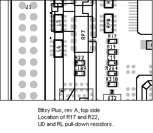
#RL_UD
Addendum: Location of Display RL and UD resistors
Some displays support flipping the LCD display vertically and/or horizontally (see topic 485 for further details).
The RL and UD signals to the display can either be hard-wired in the display cable to the panel voltage(PNL_PWR) or ground, or they can be connected to the PNL_RL and PNL_UD signals.
If you choose connect the PNL_RL and PNL_UD signals, your Bitsy Plus must have a couple pull-up or pull-down resistors populated for the display you are using.
The RL/UD resistors are in approximately the same location as on the Bitsy (see these illustrations). The following diagrams show details of where the resistors are located on the Bitsy Plus, revision A:
  |
|
|
|
ctacke
877 Posts |
Posted - 05 May 2003 : 11:16:29
|
Update
We updated the Bitsy Plus User's Manual. The link above now points to the Rev A manual. |
|
|
|
akidder
1519 Posts |
Posted - 13 May 2003 : 16:23:14
|
Erratum: Personality Board Schematic Number
The part number for the Personality Board listed incorrectly in sections 4.5.2 (two entries) and 5.5.3. The personality board schematic part number should be 640111-8000, not 170111-8000 as listed. The schematic number is printed correctly in section 4.1.5.
The Bitsy personality board schematic and bill of material are posted at topic 408 on these forums.
|
|
|
| |
Topic |
|