| Author |
Topic |
|
|
akidder
1519 Posts |
 Posted - 06 Jul 2004 : 19:30:18 Posted - 06 Jul 2004 : 19:30:18


|
VGX User's Manual ( PDF 917kB) PDF 917kB)
The VGX is a full-featured single board computer using the Intel PXA255 RISC microprocessor and the Silicon Motion SM501 graphics accelerator. The VGX is similar to the AGX in that it features a quad UART, 10/100 Ethernet, USB host and function ports. It also includes two CAN controllers.
Changes, updates and errata for this document will appear as replies to this topic as they become available.
Related topics: CE files page, mechanical drawings, Linux kernel downloads, VGX Connector Board
VGX Revision History
The following is an overview of the revision history of the VGX. The board revision is the last character in the number printed in the board copper that begins with "170116-2000".
Rev F
- RoHS construction
- Reduced EMI
Rev E
- Improved USB host performance
- LVDS options support a wider range of displays
Rev D
- Add support for Intel P30 flash
- Change Ethernet signal routing between RJ45 and J9.
Revision D of the VGX, released in 2005, makes a number of changes to the Ethernet signals. Most notably, the Ethernet signals are hard-routed either to the RJ-45 socket or to header J9 for off-board use, and not to both at the same tme. We found that the "Y" of the signal paths created stubs that made high-speed operation unreliable under some conditions. (ref topic 1868)
Rev C
- Battery socket replaces soldered RTC battery
- Improved USB and Ethernet performance
- Supports 24-bit LVDS displays
Rev B
- Supports 18-bit LVDS displays
- Improved power management
Rev A
- Reduced sleep current
- J16 changes from 10-pin header to 16-pin socket
Rev 2
- Initial release
 Subscribe! Subscribe!
You can get automatic email notifications when this, or any Topic is changed or replied to. Simply click the "Subscribe" icon ( ) on the Topic, Forum, or Category list to subscribe. You can unsubscribe ( ) on the Topic, Forum, or Category list to subscribe. You can unsubscribe ( ) just as quickly. ) just as quickly.
To cancel or manage subscriptions, click the "My Subscriptions" menu item at the upper right of any Forum page.
Edited by akidder 4-Jun-2008: Add revision history.
Edited by twhite 22-Jun-2012: Added more details about the Rev D changes.
|
|
|
akidder
1519 Posts |
 Posted - 04 Mar 2005 : 17:53:04 Posted - 04 Mar 2005 : 17:53:04


|
#Off-board_Ethernet
Design Update: Using the Off-board Ethernet Signals (J9)
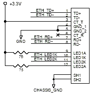
- The diagram in section 4.5.4 of the VGX Users's Manual illustrates the TX center-tap line (CT_T) capacitively coupled to 3.3V. This is an error. We have found that similar designs with this capacitor sometimes have trouble connecting to older 10BT hubs.
If you already include this capacitor in your off-board-Ethernet design, replace it with a shunt or zero-ohm resistor, or otherwise connect it directly as shown below.

- Customers who have used the off-board Ethernet connection have found that they need to force the driver to run at 10 Mbps. We believe that this is because the digital Ethernet signals are not designed to run very far without the AC isolation that the transformer offers.
|
 |
|
|
akidder
1519 Posts |
 Posted - 21 Apr 2005 : 18:13:42 Posted - 21 Apr 2005 : 18:13:42


|
#Eth_signals_J9
Connecting Cables to Header J9
As a follow-up to the previous post, note that connecting any cable to header J9 may negatively affect the Ethernet signals.
If you plan to connect a cable to header J9 and want to run Ethernet reliably at 100 Mbps, don't connect pins 19 through 22 to the cable. If you are using a ribbon cable, trim the conductors right at the J9 connector. |
 |
|
|
akidder
1519 Posts |
 Posted - 01 Jul 2005 : 18:16:36 Posted - 01 Jul 2005 : 18:16:36


|
#audio_refs
Correction: Audio references
The audio references in section 4.4 have a couple errors. The microphone and speaker connections are on J15 (not J10) and the HP_IN signal is on J4.16 (not J3.32).
To connect speakers, ground the HP_IN signal and connect speakers across the +/- pins of the right and/or left channels. |
 |
|
|
akidder
1519 Posts |
 Posted - 09 Aug 2005 : 13:25:43 Posted - 09 Aug 2005 : 13:25:43


|
#JP4_13-14
Correction: JP4 Serial 2 CTS
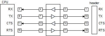
The VGX user's manual omits a shunt setting for Serial 2 EIA/TIA-232 operation. Without shunt 13-14 in place, the VGX will not respond correctly to CTS handshaking input.
The "JP4 Shunt Settings" for EIA/TIA-233 should read, "1-2, 3-4, 7-8, 9-10, 11-12, 13-14, 15-16, 17-18."
Existing VGX development and production systems currently ship with shunt 13-14 in place as shown in the following diagram of how the pins of JP4 are connected:

|
 |
|
|
akidder
1519 Posts |
 Posted - 13 Sep 2005 : 17:27:03 Posted - 13 Sep 2005 : 17:27:03


|
#Low-impedance_AD
Low A/D Input Impedance
Some customers have noted that A/D inputs ANIN1 to ANIN3 on header J8 have a 1k input impedance instead of the 43.2k documented in the user manual (ref). This issue is due to some resistors that were populated incorrectly. Those resistors are removed in systems shipping after September 2005.
If this issue affects your VGX-based product, email us with details and we will be glad to work with you to find a resolution that meets your requirements. |
 |
|
|
akidder
1519 Posts |
 Posted - 27 Oct 2006 : 12:29:46 Posted - 27 Oct 2006 : 12:29:46


|
#SSP_routing
SSP Signal Routing on VGX
The following diagram illustrates how the SSP signals are routed on the VGX via resistor packs R615 and R619. The SM501 is routed out to J9, while the PXA255 SSP ports talk to the touch panel controller and the ADSmartIO controller.
The standard signal routings are shown. Other configurations require either disabling ADSmartIO functionality or changing the OS drivers to communicate with the ADSmartIO drivers through the SM501. |
|  |
|
 |
|
|
akidder
1519 Posts |
 Posted - 14 Aug 2008 : 11:03:05 Posted - 14 Aug 2008 : 11:03:05


|
VGX Revision History
We've added the VGX revision history to the top post. I have added rev F details today. |
 |
|
|
akidder
1519 Posts |
 Posted - 06 May 2010 : 17:55:00 Posted - 06 May 2010 : 17:55:00


|
#early_VGX_boot_hang
Occasional Power Supply Issues with Early VGXs
Under some conditions, it's possible that the power supplies on older revisions of the VGX don't sequence as expected. This can result in poor power supply performance and occasional failure to boot completely.
Background
The VGX uses both linear and switching power supplies in parallel. The linear is used for startup and sleep modes, while the switcher handles the load current during run conditions.
When the load on the 3.3V supply is low, the switching power supply may not turn on. This primarily occurs when there is no external connection to the board (e.g. no LCD display, I/O) or when the board is running at a less than the full clock rate. When these conditions are present, rapid power cycling (where the onboard supply capacitors don't fully discharge) or other startup conditions may result in only the linear supply powering the VGX.
The linear power supply may be able to provide enough current for some, but not all, of the boot process, resulting in a partial boot or reset.
Detection
You can detect this condition by probing a 3.3V test point on the VGX (e.g. LCD power select). The expected voltage during operation is in the 3.3 to 3.4V range. If you see lower voltages, it suggests that only the linear regulator may be running.
Resolution
If this condition occurs with your VGX, test for the issue by adding a small load to the 3.3V power rail to see if the boot behavior changes. You can contact us to discuss your findings.
Current VGX releases use a slightly higher voltage on the 3.3V power rail. We only expect to see this issue arise with rev A and earlier VGX systems.
|
 |
|
| |
Topic |
|
|
|