| Author |
Topic |
|
|
KnowledgeBase
296 Posts |
 Posted - 01 Mar 2002 : 16:39:02 Posted - 01 Mar 2002 : 16:39:02


|
Graphics Master User's Manual (PDF , 1.17MB) , 1.17MB)
Changes, updates and errata will appear as replies to this topic as they become available.
------------------
ADS Knowledge Base
Did you know?
You can get automatic email notifications when this, or any Topic is changed or replied to. Simply click the "Subscribe" icon ( ) on the Topic List page (back one from here) on the right side of the Topic to which you would like to subscribe. ) on the Topic List page (back one from here) on the right side of the Topic to which you would like to subscribe.
You can cancel or manage your subscriptions at any time from the "My Subscriptions" menu item at the upper left of any Forum page. |
|
|
akidder
1519 Posts |
Posted - 04 Mar 2002 : 18:53:36
|
Erratum: Serial A RX line mislabeled.
The signal name for pin 23 of J20 should be listed as "RXDA".
Applicability: Revisions A and B of the Graphics Master Users Manual
|
 |
|
|
akidder
1519 Posts |
Posted - 13 Mar 2002 : 18:06:13
|
#3Vbatt
The 3V battery input is not recommended for powering the system when asleep.
Please refer to this updated information for details.
|
|
|
|
akidder
1519 Posts |
Posted - 29 Mar 2002 : 07:31:13
|
#Using_USB
Addendum: Using USB
This excerpt from the next revision of the manual gives more details about how use the USB hardware on the Graphics Master.
Using USB, 3pp (PDF, 30kB)
|
|
|
|
akidder
1519 Posts |
Posted - 02 Apr 2002 : 19:12:22
|
#GPIO_SSP
Addendum: Multiple functions of GPIO25 and 26
GPIO25 and 26 have several uses on the Graphics Master:- Driving LED2 and LED3
- General purpose I/Os (J7 pins 32 and 34)
- SSP Port (also on on J7 pins 32 and 34), GM rev C
The SSP, GPIO and LED signals are connected as shown in the following diagram (*) (the SSP lines are not connected on revisions A and B of the GMaster):
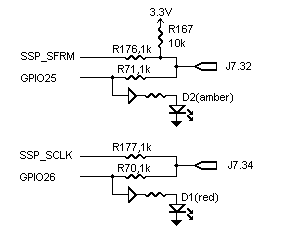
Overlap of SSP and GPIO signals on the same output pin requires that either one set of resistors be removed or that one set of signals be configured as inputs. Standard evaluation systems currently have all resistors populated. Configuration of the I/O lines is dependent on the operating system build.
If you configure GPIO25 and GPIO26 as inputs, note the following:- The signals at J7 have 1k series resistance, which protects against signal contention during boot (current ADS boot code for all operating systems configures these GPIO lines as outputs during boot)
- The LEDs have their own electrical buffers. Once the StrongARM ports are configured as inputs, the LEDs will indicate the status of the external signal with no additional current draw.
(*) The SA1111 companion chip supports two functions for C4, C5: They can be general-purpose IOs (GPIOs) or part of the SA1111 synchronous serial port(SSP). GPIO25 and 26 are GPIOs from the SA1110 processor.
Edited by akidder 27-Aug-2002: Add diagram and update text to clarify contention issues.
Edited by akidder 30-Aug-2002: Add C4 and C5 to diagram and add notes about SA1110 vs. SA1111 outputs.
Edited by akidder 14-May-2003: Strike text concerning revisions A and B. This circuit is used on all revisions of the Graphics Master. |
|
|
|
akidder
1519 Posts |
Posted - 07 May 2002 : 13:54:18
|
#GM_J20_SerialAB
Addendum: J20 Serial A and B
Serial ports A and B are populated as RS-232 on standard production systems. Other options are available in volume production.
Important Note: The RS-232 drivers for Serial A and B are powered only when there is a valid RS-232 input present. You can force the transmitters on by connecting 5V (or 3 to 12V) on any one of the five inputs (usually DCD or RI, but also DSR, CTS or RX).
For further details, see topic 224. |
|
|
|
akidder
1519 Posts |
Posted - 28 May 2002 : 14:47:51
|
#powerfailsupercaps
Addendum: Supercaps and Cutting the Power on Rev C Systems
Revision C of the Graphics Master adds a supercapacitor circuit that allows the system to ride out unexpected power interruptions. This gives the Graphics Master "pulled-plug" power protection, as it holds the 5V power up long enough for the system to shut down and go to sleep (the operating system must detect the power failure and initiate sleep mode for this to work).
If you reconnect power while the system is in sleep mode (running from supercap power), the system will remain asleep. You can choose to wake up the system by shorting the pins of J1 ("wakeup"), or can restart the system entirely by pressing the reset button SW1 ("warm boot").
Each operating system handles power management differently. For details about using this feature in Windows CE, see this topic. |
|
|
|
akidder
1519 Posts |
Posted - 28 May 2002 : 15:19:00
|
#JP5power
Clarification: Setting JP5 when Sleep Mode Not Used
JP5 selects the source of power for the system during sleep. Even if you do not plan to use sleep mode, for reliable operation, select a source of power that is always energized.
Position 1-2 (5V input) is a safe bet because it's always available when the computer is running. |
|
|
|
KnowledgeBase
296 Posts |
Posted - 24 Jul 2002 : 11:40:11
|
#J1708
Erratum: J1708 Shunt Settings
The user manual shows the wrong settings for using J1708. JP8 and JP11 should be set to 1-2 for J1708 operation.
------------------
ADS Knowledge Base |
|
|
|
akidder
1519 Posts |
Posted - 09 Aug 2002 : 19:13:51
|
#temperature_sensor
Addendum: Temperature Sensing Functionality of PA4/COL4
ADSmartIO port PA4/COL4 (J7, pin 25) includes a temperature sensing circuit. This sensor changes the behavior of the port for A/D operation compared to other ADSmartIO ports.
The Thermistor Circuit
The Graphics Master uses a thermistor to measure temperature. You can attach an external thermistor to J25 for remote sensing if the onboard sensor is removed. Read the temperature sensor using the ADSmartIO ReadTemperature() function.
As shown in the drawing below, a transistor energizes the thermistor to make a reading. This allows the controller to energize the circuit only during readings, reducing self-heating of the thermistor. Node "PA4" in this drawing connects directly to the ADSmartIO controller, and connects to J7 through a 1k resistor.
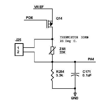
Using PA4/COL4 for A/D Readings
While useful for temperature sensing, this circuit affects A/D readings made using PA4/COL4. The circuit, in conjunction with the 1k series input resistor, presents a 77% voltage divider to A/D signals connected to J7.
There are several ways to work around this:- Where practical, use a different A/D input channel
- Compensate for the voltage divider in software by multiplying by 1.3
- Remove R264. It is located on the underside of the board at the corner by the compact flash socket. Be careful, as damage that occurs during rework is not covered under warranty. This work should only be performed at facilities that have surface-mount rework capabilities.
- Connect the A/D signal to J25.2 (bypasses the series input resistor)
- For volume production, depopulate the temperature circuit
|
|
|
|
akidder
1519 Posts |
Posted - 14 Feb 2003 : 14:07:34
|
Addendum: RqOnOff Input
Revisions C and later of the Graphics Master add debounce circuitry to the RqOnOff input signal. The effect of this circuit change is two-fold:- The steady state logic level of the input is now "high". In previous revisions, the steady state condition of this signal was logic "low".
- The circuit generates a brief pulse suitable for triggering interrupts. Polling RqOnOff will (almost) always return a logic high.
This change is transparent to most applications, as most operating systems use this input to generate an edge-detected interrupt.
For applications that already poll the RqOnOff signal (e.g. to require users to hold the power button down to turn "off"), there are several options available:- You can use interrupts generated by the RqOnOff input to look for a "code sequence" (e.g. "press the power button three times within five seconds to turn the system off")
- As a factory option to production systems, ADS can manufacture rev. C Graphics Master systems using the no-debounce circuit from rev. B
- In production volume, ADS may be able to change the debounce circuit to better meet your application needs.
Contact us if your application has requirements that are not met by the standard RqOnOff circuit.
|
|
|
|
akidder
1519 Posts |
Posted - 18 Feb 2003 : 11:32:29
|
#differential_serial
Addendum: RS-485/422/J1780 Modes: Hardware and Software Driver Settings
Configuring Serial Port 1 for use as RS485/422/J1708 requires a combination of hardware settings and software drivers to achieve the targeted mode of operation.
Hardware
Hardware shunts JP9, JP10, JP14 and JP15 redirect the StrongARM communication signals from the single-ended RS-232 transceivers to the differential transceivers used for RS485/422/J1708.
Shunts JP8 and 11 select between full and half duplex RS485/422.
Software Drivers
The software drivers must configure the Receive and Transmit Enable signals for the differential transceivers according to the mode used by the application:
 Mode    Duplex    Receiver          Transmitter
---------------------------------------------------------------------
 RS422    full     always on         always on
 RS422    half     optionally off    always on
                   during Tx
 RS485    full     always on         Hi-Z when not transmitting
 RS485    half     optionally off    Hi-Z when not transmitting
                   during Tx
 J1708   (half)   (always on)      ( automatically on for "0"
                                     bits and Hi-Z otherwise   )
"Hi-Z" means high impedance. The transmitter is effectively not connected to the network.
The driver must configure the state of the Enable lines for the desired mode. It can also decide whether in half-duplex mode the transmitter will be enabled (if so, the application will receive back what it just transmitted). See this topic for an example.
Note that J1708 automatically controls the Transmit and Receive Enable lines. No software control is required.
|
|
|
|
akidder
1519 Posts |
Posted - 24 Mar 2003 : 09:56:16
|
#J16J17
Erratum: J16 and J17 Reversed in Mechanical Drawing
In revision B of the user manual (document #110110-9001B), the mechanical drawing on page 32 of the Graphics Master shows the locations of J16 and J17 reversed.
J17 should be shown next to the power connector (J5) and J16 should be shown between the PS/2 keyboard connector (J6) and the backlight connector (J13).
The reference designators are silkscreened correctly on the board itself. |
|
|
|
akidder
1519 Posts |
Posted - 10 Apr 2003 : 14:10:03
|
Addendum: Audio Output Power
The Graphics Master uses the Philips UCB1200 for its audio codec. The UCB1200 drives up to 0.28W into an 8 ohm speaker and 0.14W into a 16 ohm load. |
|
|
| |
Topic |
|