| Author |
Topic |
|
|
akidder
1519 Posts |
 Posted - 28 Jul 2003 : 17:30:15 Posted - 28 Jul 2003 : 17:30:15


|
AGX User's Manual ( PDF 450kB) PDF 450kB)
The AGX is a full-featured single board computer using the Intel PXA255 RISC microprocessor. The AGX features a quad UART, 10/100 Ethernet, USB host, client and OTG and many other features.
The AGX includes the factory option to populate an Epson display controller with LCD, VGA and NTSC outputs and support for larger displays. However, ADS currently recommends use of the VGX for advanced graphics performance.
Changes, updates and errata for this document will appear as replies to this topic as they become available.
Related topics:
AGX CE files page
AGX mechanical drawings
Linux kernel downloads
Also see the Forum Topic Index
Did you know?You can get automatic email notifications when this, or any Topic is changed or replied to. Simply click the "Subscribe" icon ( ) on the Topic, Forum, or Category list to subscribe. You can unsubscribe ( ) on the Topic, Forum, or Category list to subscribe. You can unsubscribe ( ) just as quickly. ) just as quickly.
To cancel or manage subscriptions, click the "My Subscriptions" menu item at the upper right of any Forum page.
Edited by akidder 6-Oct-2003: Update with revision 2 of manual and link to CE files topic.
Edited by akidder 4-Apr-2005: Update description to indicate that Epson display controller is a factory option.
|
|
|
akidder
1519 Posts |
 Posted - 06 Oct 2003 : 15:33:37 Posted - 06 Oct 2003 : 15:33:37


|
Update: Manual revision 2
We've updated the manual with more details about the AGX. Download it from the link above. |
 |
|
|
akidder
1519 Posts |
 Posted - 16 Dec 2003 : 17:39:17 Posted - 16 Dec 2003 : 17:39:17


|
Erratum: J19 LCD Connector (Hirose)
Revision 2 of the AGX user manual (110115-40012) incorrectly states the function of pin 28 of J19. The correct label should read:J19 Pin 28: "Panel power"(PNL_PWR) |
 |
|
|
akidder
1519 Posts |
 Posted - 19 Dec 2003 : 09:04:22 Posted - 19 Dec 2003 : 09:04:22


|
Transitioning from the AGC
If you have an AGC and and are planning to transition to the AGX, the following document may provide guidance. It is an excerpt from the AGX manual that describes the basic differences between the two products.
Changes from AGC to AGX: PDF (1 page)
|
 |
|
|
akidder
1519 Posts |
 Posted - 22 Dec 2003 : 16:19:22 Posted - 22 Dec 2003 : 16:19:22


|
#AGX_PCMCIA_ejector
PCMCIA Ejector Hardware for AGX
While it is a production option, AGX development systems typically don't include the PCMCIA ejector hardware.
If you need it, we can send you an ejector assembly for your development system. The part number is AMP 146019-1 (ADS stock number 250080-00002).
For production orders, be sure to specify ejector hardware for your AGX; additional charges may apply for this option.
Email us for details.
|
 |
|
|
akidder
1519 Posts |
 Posted - 02 Mar 2004 : 12:51:09 Posted - 02 Mar 2004 : 12:51:09


|
#AGX_I2C
AGX I2C Components
If you plan to use I2C and are using an AGX system built before March 2004, you may need to update the AGX hardware. Use the following documents to determine if the recommended I2C components are installed on your system:Locating the parts (GIF)
Schematic with part numbers (GIF) In particular, we have recently updated the value of pull-up resistors R486 and R487 to meet the I2C specifications under a wider variety of conditions.
If you need to replace the I2C components on your AGX, please contact us with details about your I2C application. |
 |
|
|
akidder
1519 Posts |
 Posted - 24 Jun 2004 : 18:19:47 Posted - 24 Jun 2004 : 18:19:47


|
#Off-board_Ethernet
Using the Off-board Ethernet Signals (J9)
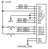
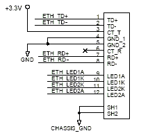
You can use the signals on J9 to locate an Ethernet socket elsewhere in your enclosure. You will need to use an RJ45 socket with integrated Ethernet transformer, such as the Pulse J0026D21B. Wire the socket as shown in either of the following diagrams:
 
Note that because these high-frequency signals are not designed to travel very far, you should not expect to drive the Ethernet on an external socket faster than 10 Mbps.
Design Updates (akidder 4mar05)- The original illustration in this post showed a capacitor in series with the TX center-tap line (CT_T). This is an error. We have found that similar designs with this capacitor sometimes have trouble connecting to older 10BT hubs.
If you already include this capacitor in your design, replace it with a shunt or zero-ohm resistor.
- Customers who have used the off-board Ethernet connection have found that they need to force the driver to run at 10 Mbps. We believe that this is because the digital Ethernet signals are not designed to run very far without the AC isolation that the transformer offers.
- We've added a second diagram that illustrates that you can either use the ETH_LEDnA outputs from the AGX to drive the anode of the LED on the Ethernet socket, or you can supply your own anode resistors. (The VGX does not supply these signals, so must use anode resistors as shown on the left.)
Edited by akidder 3-Mar-2005: Add Design Updates |
 |
|
|
akidder
1519 Posts |
 Posted - 28 Jun 2004 : 16:31:39 Posted - 28 Jun 2004 : 16:31:39


|
#ANIN0
Analog Input ANIN0 Not Currently Supported
Analog Input Zero (ANIN0) on J8 pin 11 connects to the touch panel controller and not to the ADSmartIO like ANIN1-ANIN3. Neither CE nor Linux currently supports ANIN0 as an analog input. |
 |
|
|
akidder
1519 Posts |
 Posted - 04 Mar 2005 : 16:59:20 Posted - 04 Mar 2005 : 16:59:20


|
Design Alert: Off-Board Ethernet Connection
If you use the off-board Ethernet signals on J9, please see the design updates described above.
|
 |
|
|
akidder
1519 Posts |
 Posted - 16 May 2005 : 11:29:25 Posted - 16 May 2005 : 11:29:25


|
#AD_PortA
Addendum: ADSmartIO Port A for A/D
Section 4.3.4 states that "not all [ADSmartIO port A] ports are available for external A/D use." This is not entirely accurate. Here's a clarification:- All eight Port A lines (PA0-PA7) can be used as analog inputs.
- I/O lines PA5-PA7 use the voltage divider specified in the electrical specifications (6.2.6), allowing input voltages of up to 10.8V.
- For lines PA0-PA4, the valid input range is 0 to Vref (2.5V). These lines include a 1k series resistor, which shouldn't affect A/D operations.
As shown in the addendum to the ADSmartIO user manual, you shouldn't need to use the SIOSelectOption() function on current ADS products. |
 |
|
|
akidder
1519 Posts |
 Posted - 09 Aug 2005 : 13:46:45 Posted - 09 Aug 2005 : 13:46:45


|
#JP4_13-14
Correction: JP4 Serial 2 CTS
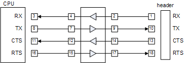
The AGX user's manual omits a shunt setting for Serial 2 EIA/TIA-232 operation. Without shunt 13-14 in place, the AGX will not respond correctly to CTS handshaking input.
The "JP4 Shunt Settings" for EIA/TIA-233 should read, "1-2, 3-4, 7-8, 9-10, 11-12, 13-14, 15-16, 17-18."
Existing AGX development and production systems currently ship with shunt 13-14 in place as shown in the following diagram:

|
 |
|
|
akidder
1519 Posts |
 Posted - 07 Jul 2008 : 16:35:52 Posted - 07 Jul 2008 : 16:35:52


|
#AGX_Reset_In
ESD Protection for Reset_In
The Reset_In signal on the AGX does not include ESD protection. If you are connecting it to an external button or expect users to have interaction with the reset input, make sure to include a transorb or other ESD protection on the input.
Note that section 6.2.1 (electrical specifications for the reset input) mistakenly lists Reset_In as being at a different location than J9 pin 16. |
 |
|
|
akidder
1519 Posts |
 Posted - 06 Sep 2012 : 16:42:41 Posted - 06 Sep 2012 : 16:42:41


|
Some AGX Won't Boot with Lower Input Voltage
Over the years we have observed that a few AGX don't boot reliably unless the input voltage is slightly elevated (5.1V or greater).
The source of this issue lies in the power supply design, and a perky, 100 mA linear regulator that does so much of the work during startup that the 3.3V switcher in parallel doesn't think it needs to turn on. Regrettably, the linear can't keep up when things get tough, and the board fails to boot.
3.3V LCDs typically provide the best load to ensure reliable starts every time. The display voltage is selected with JP1. Where the display is 5V-only, give us a call and we can discuss ideas for adding a small additional load.
This fault typically occurs in a very small percentage of units, and only under specific conditions, so shouldn't be a concern for most applications.
|
 |
|
| |
Topic |
|