| Author |
Topic |
|
|
KnowledgeBase
296 Posts |
 Posted - 01 Mar 2002 : 16:34:37 Posted - 01 Mar 2002 : 16:34:37


|
Graphics Client Plus User's Manual ( PDF, Revision B, March 2001) PDF, Revision B, March 2001)
Changes, updates and errata will appear as replies to this topic as they become available.
------------------
ADS Knowledge Base
Did you know?You can get automatic email notifications when this, or any Topic is changed or replied to. Simply click the "Subscribe" icon ( ) on the Topic List page (back one from here) on the right side of the Topic to which you would like to subscribe. ) on the Topic List page (back one from here) on the right side of the Topic to which you would like to subscribe.
You can cancel or manage your subscriptions at any time from the "My Subscriptions" menu item at the upper left of any Forum page. |
|
|
akidder
1519 Posts |
Posted - 13 Mar 2002 : 18:09:07
|
The 3V battery input is not recommended for new designs.
Please refer to this updated information for details.
-----------------------
Drew Kidder
ADS Technology Transfer |
 |
|
|
akidder
1519 Posts |
Posted - 13 Mar 2002 : 18:17:15
|
#serial1_shunts
Erratum: Serial 1 shunts not shown in correct order
The table of shunts in section 3.6.7 lists the Serial 1 shunts in the wrong order. The top row should be listed as JP11, JP8, JP10, JP9.
Shunts JP15 and JP14 are pictured correctly, and the labels silkscreened on the Graphics Client Plus are correct.
-----------------------
Drew Kidder
ADS Technology Transfer |
|
|
|
akidder
1519 Posts |
Posted - 23 Jan 2003 : 11:53:28
|
Specification Change: PCMCIA 12V Disconnected
Due to issues with some wireless cards (e.g. with Cisco Aironet), we no longer connect the 12V input power from J5 pin 4 to the PCMCIA socket(J11). This is accomplished by removing Q7, which is located on the bottom of the GC Plus under the PCMCIA header.
This change was phased into our stock effective April 2002.
|
|
|
|
akidder
1519 Posts |
Posted - 18 Feb 2003 : 11:37:23
|
#differential_serial
Addendum: RS-485/422/J1780 Modes: Hardware and Software Driver Settings
Configuring Serial Port 1 for use as RS485/422/J1708 requires a combination of hardware settings and software drivers to achieve the targeted mode of operation.
Hardware
Hardware shunts JP9, JP10, JP14 and JP15 redirect the StrongARM communication signals from the single-ended RS-232 transceivers to the differential transceivers used for RS485/422/J1708. Shunts JP8 and 11 select between full and half duplex RS485/422.
Software Drivers
The software drivers must configure the Receive and Transmit Enable signals for the differential transceivers according to the mode used by the application:
 Mode    Duplex    Receiver          Transmitter
---------------------------------------------------------------------
 RS422    full     always on         always on
 RS422    half     optionally off    always on
                   during Tx
 RS485    full     always on         Hi-Z when not transmitting
 RS485    half     optionally off    Hi-Z when not transmitting
                   during Tx
 J1708   (half)   (always on)      ( automatically on for "0"
                                     bits and Hi-Z otherwise   )
|
"Hi-Z" means high impedance. The transmitter is effectively not connected to the network.
The driver must configure the state of the Enable lines for the desired mode.� It can also decide if, in half-duplex mode the transmitter will be enabled (if so, the application will receive back what it just transmitted)(see this topic for an example).
Note that J1708 automatically controls the Transmit and Receive Enable lines. No software control is required.
|
|
|
|
akidder
1519 Posts |
Posted - 27 Feb 2003 : 07:32:28
|
Addendum: J1708 Jumper Settings
J1708 is available as a factory option on revision D and later of the Graphics Client Plus.
If your system has J1708 installed, configure the jumpers on the GC Plus the same as for half-duplex RS-485 operation. |
|
|
|
akidder
1519 Posts |
Posted - 28 May 2003 : 15:31:55
|
#RTC
Addendum: Real-Time Clock Feature (uses PB0 and PB1)
Revision D and later of the Graphics Client Plus features a battery-backed real-time clock (RTC) chip. This allows the GC Plus to maintain the time and date when all other power is disconnected from the board. The GC Plus uses ports PB0 and PB1 (SMTIO0 and SMTIO1) to communicate with the RTC (a Dallas DS1307) as shown in the following diagram:
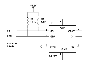
PB0 and PB1 cannot be used for general purpose I/O if the system uses the real-time clock.
Revision D boards use a header (J21) for supplying backup power to the RTC. Pin 1 of J21 is the positive input (pin 1 is the square pad on the underside of the board). Revision F boards solder a long-life battery to the board; they have the option of replacing the battery with J21.
If using J21 to power the RTC, connect a 3.0V battery (2.0 to 3.5V is the valid voltage range). Because the RTC draws a very small amount of current (500nA, max.), the battery will last as long as its normal shelf life. Use fresh batteries rated for the temperature service of your product, and use Lithium ion batteries for longest life.
Use standard electronics precautions when handling GC Plus boards. Be careful not to place the GC Plus on a metallic surface, as this may short and discharge the RTC battery.
|
|
|
|
akidder
1519 Posts |
Posted - 15 Jul 2003 : 16:58:10
|
#GCP_F_serial_jumpers
Addendum: Location of Revision F Serial 1 Jumpers
Revision F of the GC Plus has a slightly different layout of the jumpers for Serial 1. The following diagram indicates the location of these three pin headers.
Note also the location of JP23, which is used to insert a terminating resistor on RS-485 networks.

(click to enlarge)
|
|
|
| |
Topic |
|